Understanding Linear Slide Travel Per Rotation

Linear slides are essential components in many industrial applications, offering precision in linear motion systems. Whether it’s in robotics, CNC machines, or packaging industries, linear slides help ensure accuracy, smooth motion, and durability. When discussing these components, one critical metric to understand is the linear slide travel per rotation—a term that describes the distance a linear slide moves in response to one complete rotation of its drive mechanism, typically a lead screw, ball screw, or a belt drive. This metric holds significant importance in determining the overall performance of a linear motion system.
In this article, we will explore the key subtopics related to linear slide travel per rotation, delve into the factors that influence this metric, and provide a comprehensive understanding of how it applies to various mechanical systems.
Key Components of Linear Slide Systems
To fully understand the concept of linear slide travel per rotation, it is important to first comprehend the basic components of a linear motion system.
1. Linear Slide (Rail)
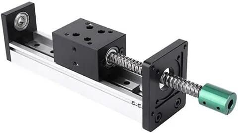
A linear slide, or rail, is a track that guides the moving element (such as a carriage or platform) along a straight path. The slide itself can be constructed from various materials like steel, aluminum, or composite materials, depending on the application. The slide ensures smooth and precise movement, reducing friction and wear over time.
2. Lead Screw or Ball Screw
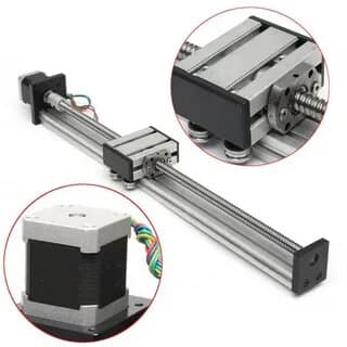
Linear slides are often powered by screws, either lead screws or ball screws. These mechanisms convert rotary motion into linear motion. A lead screw typically consists of a threaded rod that meshes with a nut, while a ball screw utilizes ball bearings to reduce friction and increase efficiency. The pitch of the screw, or the distance between the threads, plays a key role in determining the travel per rotation.

3. Belt Drives
In some applications, belt drives are used instead of screws. A motor rotates a pulley system that moves a belt, which in turn drives the slide forward or backward. Belt drives tend to offer faster motion over longer distances, though they may sacrifice some precision compared to screw systems.
4. Stepper or Servo Motors
The rotary motion that drives the linear slide is typically generated by a motor—either a stepper motor or a servo motor. Stepper motors rotate in discrete steps, making them ideal for applications requiring precise control of linear travel. Servo motors provide continuous feedback and are often used in more complex or high-speed applications.
What is Linear Slide Travel Per Rotation?
Linear slide travel per rotation refers to the distance the slide moves linearly for every full revolution of the drive mechanism (screw or pulley). This measurement depends primarily on the following factors:
- Pitch of the Lead/Ball Screw: The pitch, measured in millimeters or inches per revolution, is the most direct determinant of how far the slide will travel with each turn.
- Belt Drive Circumference: In belt-driven systems, the diameter of the pulley or wheel determines the distance the belt, and thus the slide, will move per rotation.
- Motor Steps or Degree of Rotation: In systems with stepper motors, the motor’s step angle also influences the travel per step or full rotation.
Formula for Linear Travel Per Rotation (for Screw-Based Systems)
For a screw-driven system, the formula to calculate the linear slide travel per rotation is:
Travel per rotation=Screw pitch×Rotational speed (rpm)\text{Travel per rotation} = \text{Screw pitch} \times \text{Rotational speed (rpm)}
This simple formula reveals that by adjusting either the pitch of the screw or the speed of rotation, the linear travel per rotation can be modified to meet specific application requirements.
Formula for Linear Travel Per Rotation (for Belt-Driven Systems)
For belt-driven systems, the travel per rotation is determined by:
Travel per rotation=Belt Circumference=π×Pulley Diameter\text{Travel per rotation} = \text{Belt Circumference} = \pi \times \text{Pulley Diameter}
In these systems, pulley diameter plays a critical role, and increasing the pulley size can result in longer travel distances per rotation.

Factors In
fluencing Linear Slide Travel Per Rotation
Several factors impact the linear travel per rotation, which must be carefully considered when designing or selecting a system for a specific application. Let’s explore these factors:
1. Screw Pitch
The pitch of a lead or ball screw is the distance between adjacent threads on the screw. This is the most direct factor influencing travel per rotation in screw-driven systems. A higher pitch (wider spacing between threads) results in greater linear travel per rotation, while a lower pitch leads to finer, more precise movement but shorter travel distances.
Example:
- A 10mm pitch screw moves the slide 10mm for every full rotation.
- A 5mm pitch screw moves the slide 5mm per rotation, offering finer control.
2. Pulley Size in Belt Drives
In belt-driven systems, the pulley diameter affects the belt’s travel per rotation. Larger pulleys result in longer linear travel, while smaller pulleys reduce the travel distance.
Example:
- A pulley with a 100mm diameter offers a travel per rotation of approximately 314mm (π × 100mm).
- A 50mm pulley, in contrast, provides only 157mm of travel per rotation.
3. Motor Type and Resolution
Stepper motors divide a full rotation into a set number of steps. The finer the steps, the more precise the control over the travel per rotation. For example, a stepper motor with 200 steps per revolution paired with a lead screw offers much finer control than a standard motor with fewer steps.
In contrast, servo motors can provide continuous rotational motion with feedback systems, leading to more dynamic control of linear travel.
4. Gear Ratios
In some systems, gear mechanisms are introduced between the motor and the screw or pulley, altering the relationship between rotation and linear travel. A higher gear ratio reduces the travel per rotation, offering finer control, while a lower ratio increases the travel per rotation.
Applications of Linear Slide Travel Per Rotation
The concept of linear travel per rotation is integral to many applications across various industries. Below are some key areas where precise control over travel is critical:
1. CNC Machines
Computer numerical control (CNC) machines rely on precise movement to cut, mill, or engrave materials like metal, wood, or plastic. The lead screws in CNC machines are designed with specific pitches to allow precise control over the cutting tools, ensuring accuracy and repeatability.
2. 3D Printers
3D printers use both belt-driven and lead screw-driven systems to control the position of the printing head or the build platform. The travel per rotation of the motors directly affects the resolution and quality of printed objects, making it a critical consideration for machine design.
3. Robotics
Robots often use linear slides to control arms or actuators, enabling them to pick, place, or manipulate objects with precision. In such applications, the travel per rotation of the system directly influences the speed and accuracy of the robot’s movements.
4. Packaging Machines
In the packaging industry, linear slides help move products or materials along an assembly line. The travel per rotation of these systems must be carefully optimized for speed, efficiency, and precision, particularly in high-speed automated systems.
Table: Linear Travel per Rotation in Various Systems
| System Type | Drive Mechanism | Travel per Rotation (Typical) | Precision | Applications |
|---|---|---|---|---|
| CNC Machine | Lead Screw | 5-10mm per rotation | High | Machining, milling, engraving |
| 3D Printer | Belt Drive/Lead Screw | 0.1-0.5mm per rotation | Very High | 3D printing of models and parts |
| Robotic Arm | Lead Screw/Ball Screw | 1-5mm per rotation | Medium to High | Precision pick-and-place operations |
| Packaging Machine | Belt Drive | 100-200mm per rotation | Medium | Automated product packaging |
| Industrial Conveyor | Belt Drive | 200-500mm per rotation | Low | Moving items on production lines |
This table illustrates how different applications demand varying levels of precision and linear travel per rotation, based on the nature of the task and the drive mechanism employed.
Frequently Asked Questions (FAQs)
1. What is linear slide travel per rotation?
Linear slide travel per rotation refers to the distance a slide moves in a straight line for every full rotation of the drive mechanism, such as a screw or belt system. It is influenced by factors like the screw pitch, pulley diameter, and motor resolution.
2. How can I calculate the travel per rotation for my system?
For a screw-driven system, multiply the pitch of the screw by the number of revolutions. In belt-driven systems, the travel per rotation is equal to the circumference of the pulley (π × diameter).
3. What is the difference between a lead screw and a ball screw?
Both lead screws and ball screws convert rotary motion into linear motion. However, ball screws use ball bearings to reduce friction, resulting in higher efficiency and longer service life. Lead screws, while less efficient, are often more cost-effective.
4. Which system offers more precision: a screw-driven system or a belt-driven system?
Screw-driven systems generally offer more precision due to the finer control over movement, especially when paired with stepper motors. Belt-driven systems provide faster motion over longer distances but may sacrifice some precision. why do police wear belts instead of slings
5. Can I adjust the linear travel per rotation in my system?
Yes, you can adjust the travel per rotation by changing factors such as the screw pitch, pulley diameter,


